The BBC and Master Computer Public Domain Library
BBC RGB to SCART Socket wiring
13/02/2000
A picture is worth 1000 words
 Now for a few words of explanation:
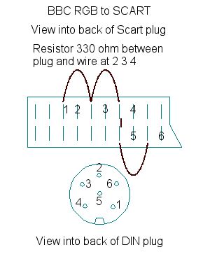
The black curved lines on the drawing of the SCART plug (there are 3
of them) indicate wires joining the pins, there is also one short line
on the drawing indicating a join between the top row of pins and the lower
row of pins on the SCART plug.
Join points 1 to 1, 2 to 2, 3 to 3, 4 to 4, 5 to 5 and 6 to 6.
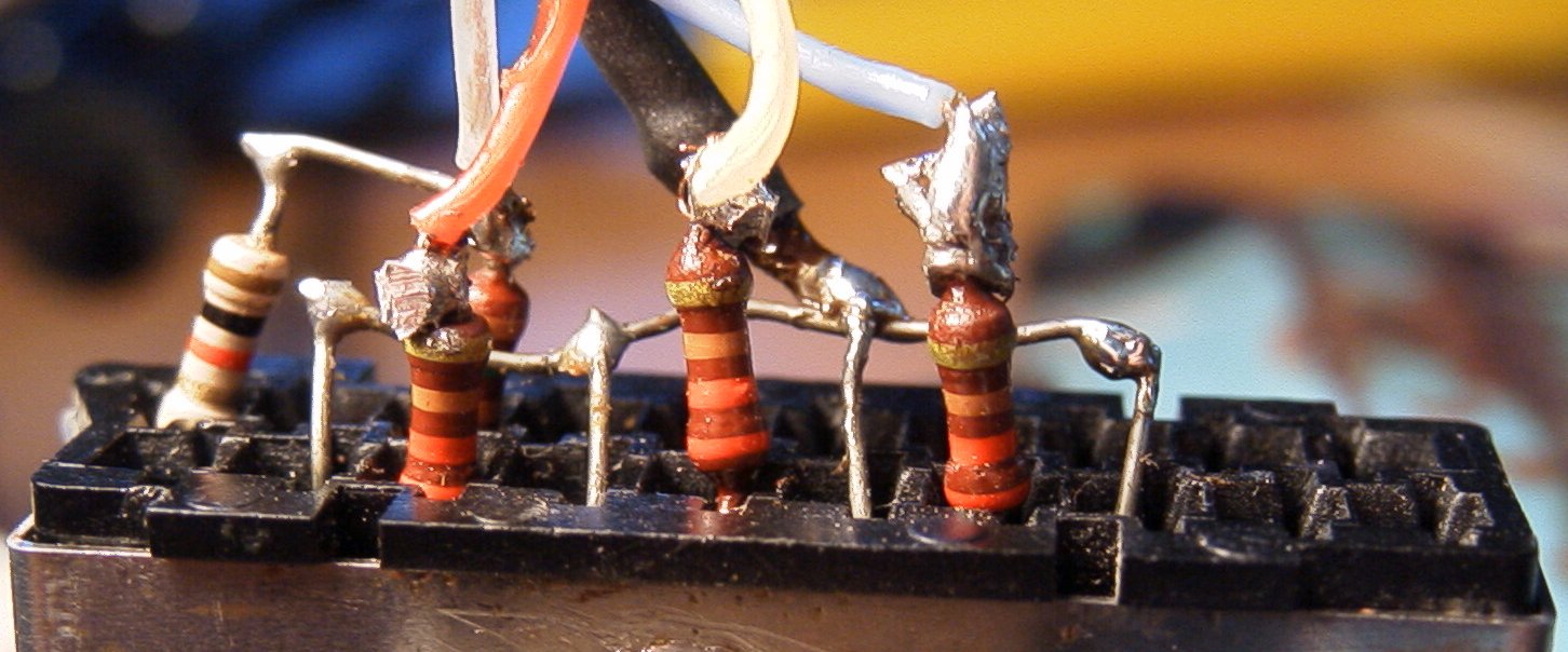
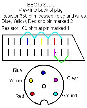
There are 3 resistors of 330W each (Orange,
Orange, Brown,Gold). These are soldered between the pin of the SCART plug
and wire that goes to the DIN plug at points 2, 3 and 4.
Remember that the views are looking into the backs of the plugs, as
if you have them in bits and are looking atthe wires.
The lead that I used to copy this from had the earth soldered to the
case of the DIN plug, but was not fastened to the SCART plug at all.
17/08/2003
Variation on the above scart lead.
This is for a Sony KVM1420U